Build Timeline
The complete project log, from first wrench to first drive. New entries added as the build progresses.
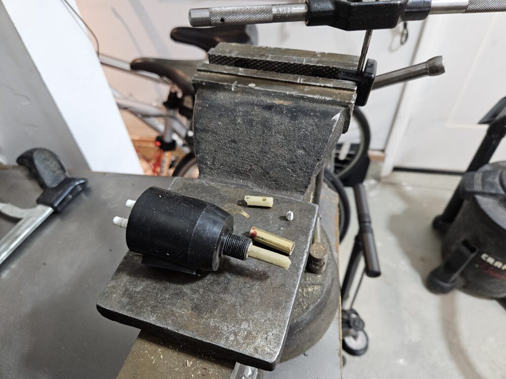
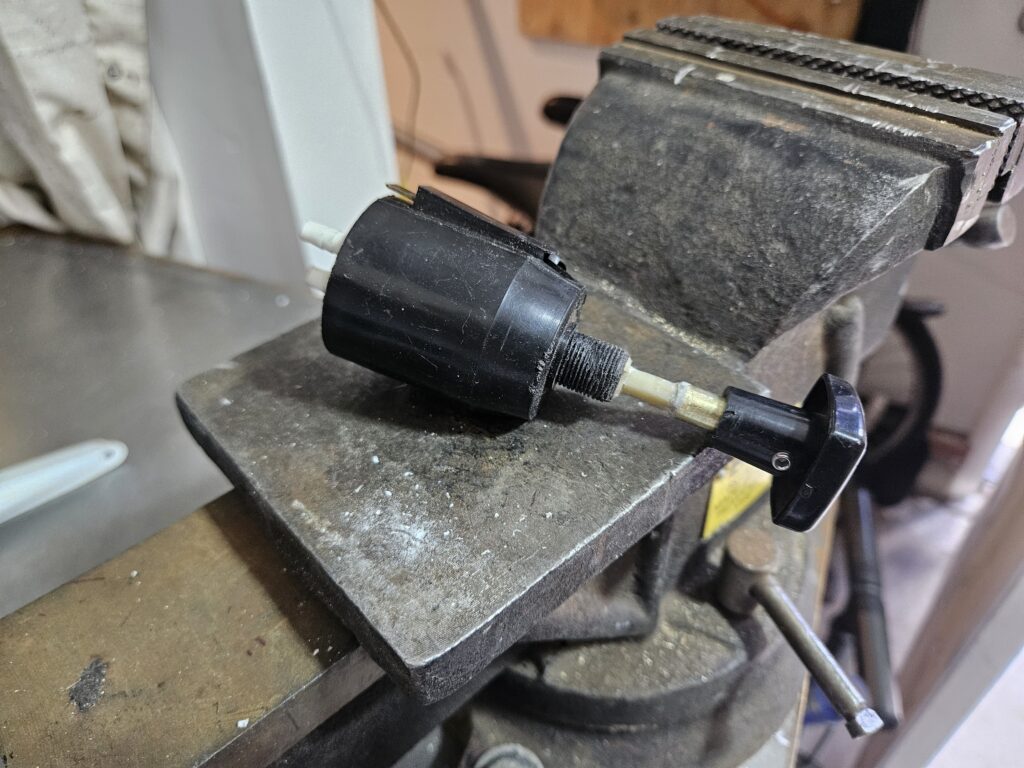
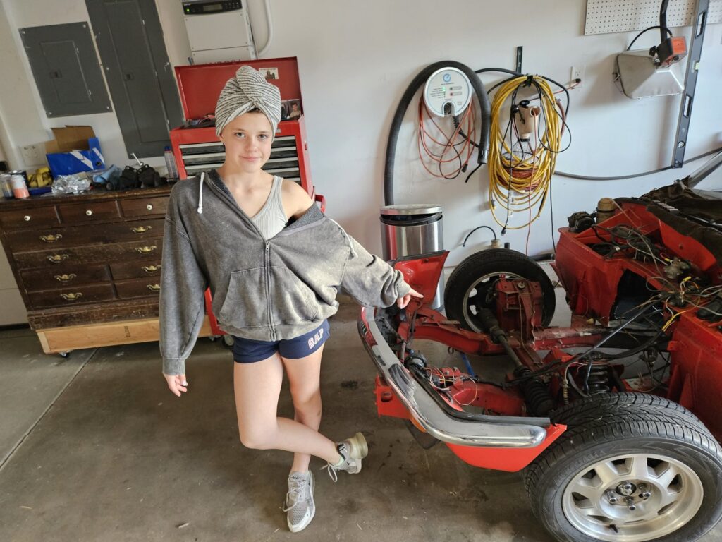
Fixing the Windshield Wiper Switch
This is a delicate part in a Spitfire. They designed a switch with a push pump for the wiper fluid that also controls the speed. As far as I know this part is no longer available. During the disassembly of the dash the switch arm broke. I decided to fix it using a brass sleeve and super glue mixed with baking soda. Shown below is the before and after photos. I used a setscrew to attach to the arm and had to drill our the switch knob a bit to fit the sleeve.
Instrument Cluster — Bench Testing and Calibration
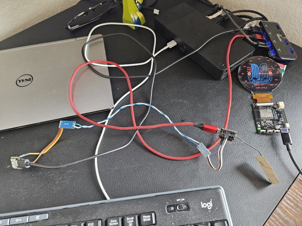
The full bench test setup for the custom instrument cluster: laptop for firmware flashing and CAN bus simulation, the ESP32-S3 display board, a CAN bus interface adapter, and test cables. The display is showing live data including 413V battery pack voltage, 53°C temperatures, and odometer reading 371 miles. Getting the CAN bus messages decoded correctly and the gauge sweep calibrated took several sessions. We faked the ZombieVerter can messages using a esp32.
Custom Instrument Cluster — Round ESP32 Display
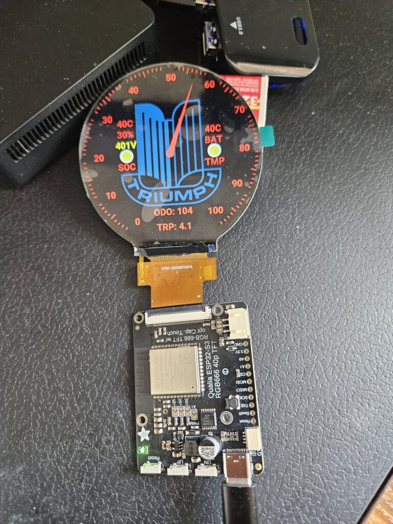
One of the most striking parts of the build: a completely custom round instrument display built on a Qualia ESP32-S3 board with a circular RGB666 TFT screen. The gauge face shows the Triumph logo in blue, a red needle speedometer, and four data readouts: SOC% (state of charge), battery voltage , battery temperature, and motor temperature. The odometer and trip meter read from the CAN bus via the ZombieVerter VCU. This replaces the entire original Triumph instrument cluster with something that looks period-correct in the round binnacle but shows EV-specific data.
The odometer has to be saved to flash. Rather than periodically store to flash we are using a digital input to indicate when 12V power has been lost to the 5V power supply. This triggers saving a json with the latest milage to flash.
All temps(inverter, motor, batteries) feed into this display and will change the alert if any are out of range. The display will flash a warning and indicate what error is occurring. Only one error can be displayed and we prioritize the batteries.
The sytem is based off a design called the ZombieVerter Display . That code is leveraged to read the from the zombieverter. The esp32 that runs the display has very few inputs so we used the wifi protocal ESPNOW to communicate between two ES32's. One makes the calls to the zombieverter then transfers the the Qualia.
We will have to see how this all works in the car.
Adding the Winter package heated seats
What do you do with a electric car that has no heat. Add heated seats. We call this the winter package, because doesn't every electric spitfire owner want to drive in the snow.
Eva and I opened up the sets and added heated seat pads. Each seat has its own controls and each has two settings. Isaac and I installed them back in the car and ran the wires. Testing proved we had some warm buts.
Sorry we didn't take any photos of this step.
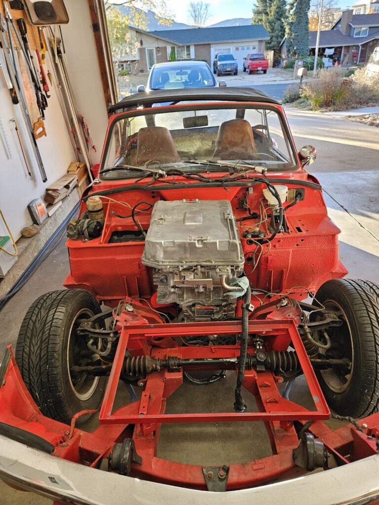
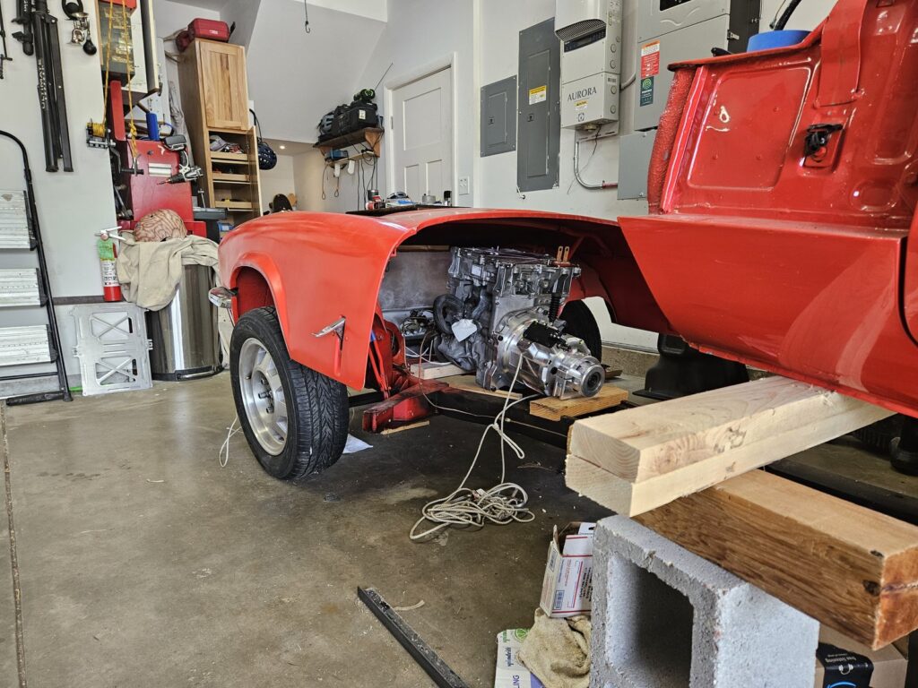
Engine Bay Complete — Body Back On
A 3/4 view of the Spitfire with the body back on and the engine bay showing the near-complete installation. The Leaf motor sits neatly in the bay, the front battery enclosure is mounted, and the brown leather interior is visible through the windscreen. The soft-top frame is up. It's starting to look like a finished car.
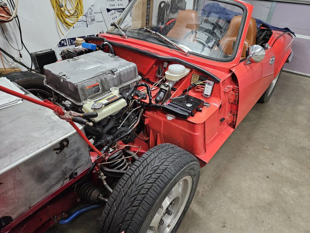
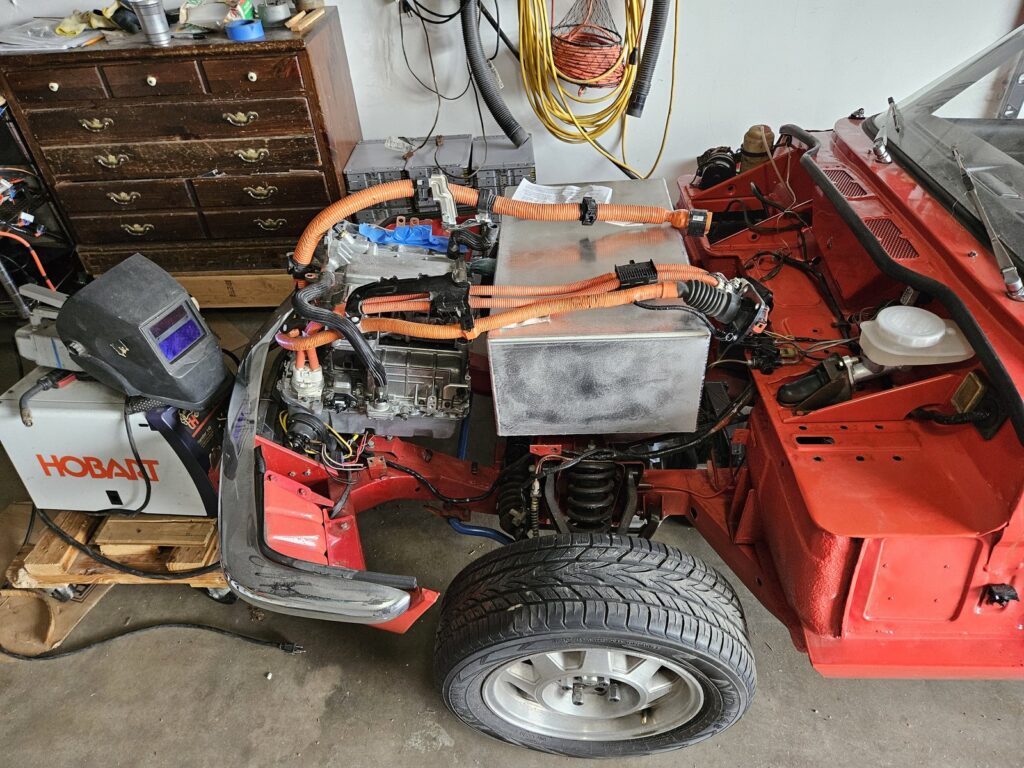
Engine Bay — Motor, Battery Box and Wiring
The engine bay filling up with hardware — Leaf motor and inverter on the right, custom front battery box on the left, and the first pass of the HV wiring loom connecting them. The orange HV cables run from the battery box to the inverter input. The low-voltage control harness for the ZombieVerter VCU is the rats-nest of smaller wires in the centre — that gets tidied up in the next phase.
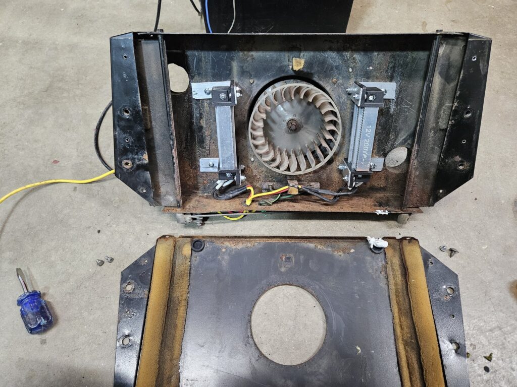
Heater Box — New Blower Fan Fitted
The original Triumph heater box disassembled and fitted with a new 12V blower fan motor. We're keeping the original heater matrix location but upgrading the fan for better airflow. An EV doesn't produce engine waste heat, so we'll add a small PTC electric heating element to warm the coolant circuit for cabin heat.
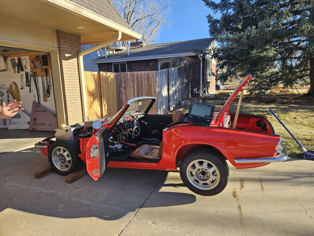
First Time in the Driveway
A big milestone: the Spitfire rolled out of the garage for the first time. Bonnet still off while we finalise HV wiring routing, but it looks unmistakably right. The wall charger inside will be its daily home juice.
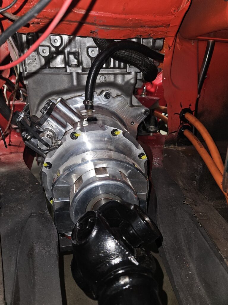
Motor Adapter Plate — The Critical Interface
The most precision-critical part of the build. The EM57 Leaf motor was connected to the torquebox using the adapter plate from TorqueTrends. It was a tight fit in the frame. We built custom engine mount points that reused the Leaf engine mounts. The box is a bit lower than we wanted. We will have to build a skid plate for it later.
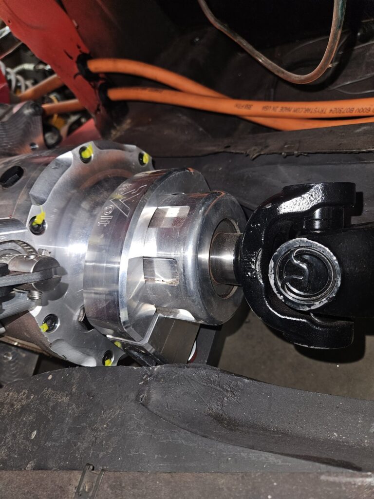
TorqueBox to Driveshaft — Coupling Detail
A close look at the TorqueBox output shaft coupling to the GT6 propshaft. The polished aluminium TorqueBox output flange mates to a freshly-painted universal joint yoke. The yellow torque witness marks confirm the fasteners are at spec. This is the mechanical link between the Leaf motor and the GT6's 3.63:1 rear differential.
Lucas Wiring — Sorting the Cockpit Loom
Deep in the original Triumph wiring loom — a classic Lucas electrical system with colour-coded British wiring. We're retaining as much of the original 12V system as possible: indicators, lights, horn, and instruments all stay. The old ignition and fuel system wiring gets removed and replaced with EV-specific controls connected to the ZombieVerter VCU.
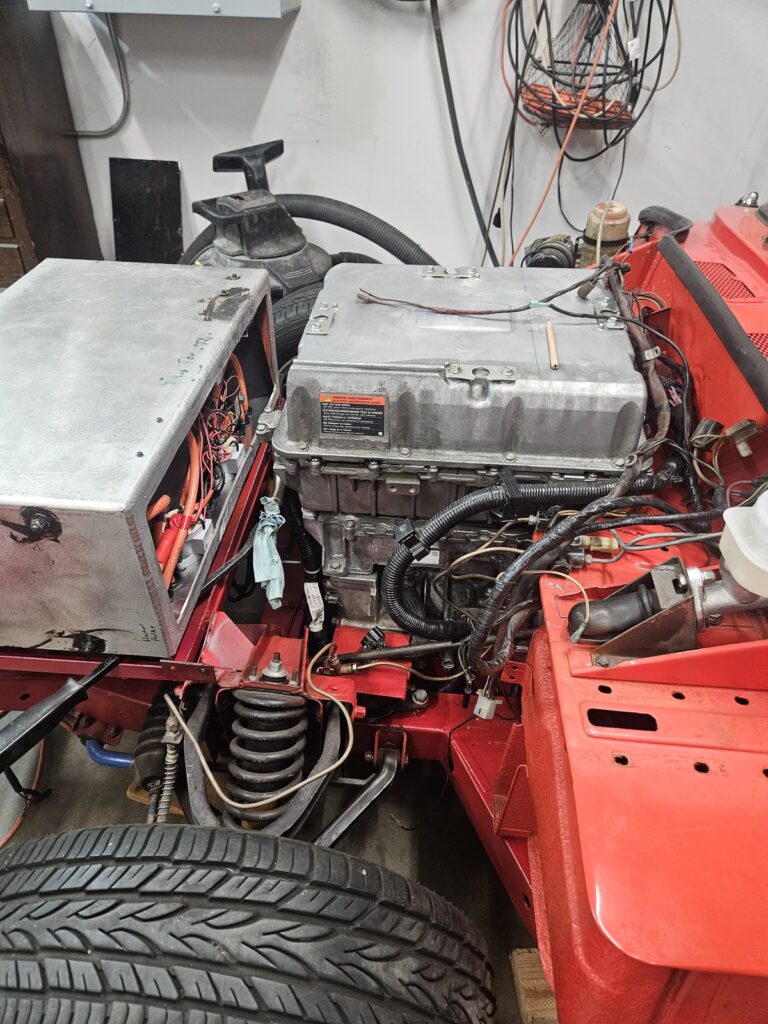
Body Back On — Motor Visible from the Front
With body reunited with chassis, the compact motor nestles neatly in a bay designed for a 1.3-litre four-cylinder. Soft-top folded, seats in — for the first time it looks like a driveable car again.
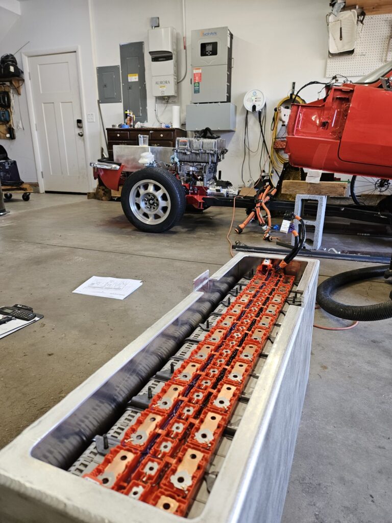
Battery Pack Assembly — Almost Complete
The main battery enclosure nearly finished, with most of the cell modules seated and the HV busbar connections made. The custom aluminium box was fabricated to exactly fit the Spitfire boot space while keeping the cells safely enclosed and thermally managed. The Leaf OBC will charge this pack at 6.6 kW from a standard J1772 outlet.
Packing the Battery Cells
Carefully loading the individual Leaf cell modules into the custom aluminium enclosure. Each module must sit square, the inter-module connections must be torqued correctly, and the cell monitoring wires must be routed without pinching. This is painstaking work — one loose connection in a 350V pack is a serious problem.
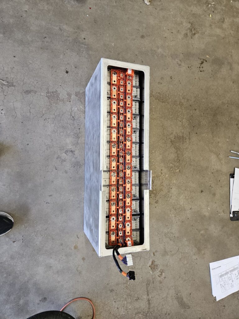
Battery Cells Loaded Into Aluminium Enclosure
The Leaf battery cells packed into the custom aluminium enclosure that will live in the Spitfire's boot. Each orange-framed cell stack is seated and the inter-cell busbars are visible running down the centre. A Nissan Leaf BMS diagram sits on the floor beside it — we referred to this constantly while wiring the cell monitoring harness.
Battery Box and Chassis — Taking Shape
The battery enclosure in the foreground with the motor-equipped rolling chassis visible in the background. At this stage both the front battery section (engine bay) and the rear enclosure (boot) are taking shape. The orange HV cables running from the motor to the battery will carry up to 400 amps under hard acceleration.
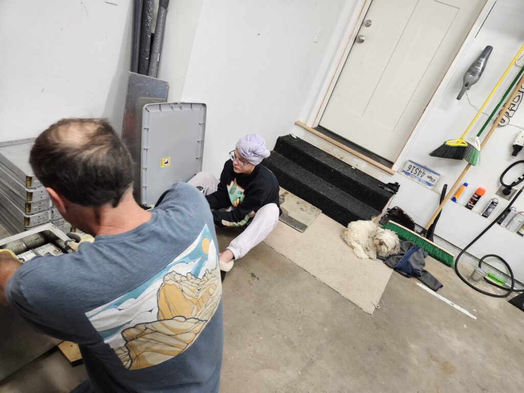
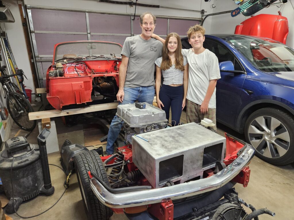
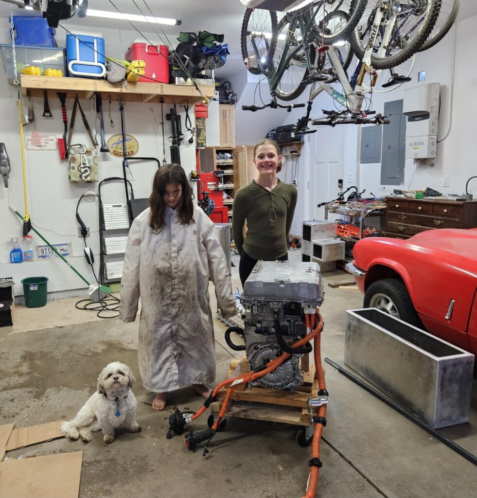
Family Build Day — The Whole Crew
One of those Saturdays where everything clicked — front battery box mounted, body coming back down, both kids in the garage helping. The Tesla in the background is a reminder that EVs don't have to be boring.
Battery Module Cell Detail
A close look inside one of the Leaf battery modules — the individual pouch cells are visible, stacked and compressed between the orange carrier frames. Each cell is a lithium NMC chemistry pouch; the entire 40 kWh pack contains 192 of these cells in a 96S2P configuration. Wiring them in series-parallel correctly while maintaining the OEM cell balancing is one of the most critical steps of the build.
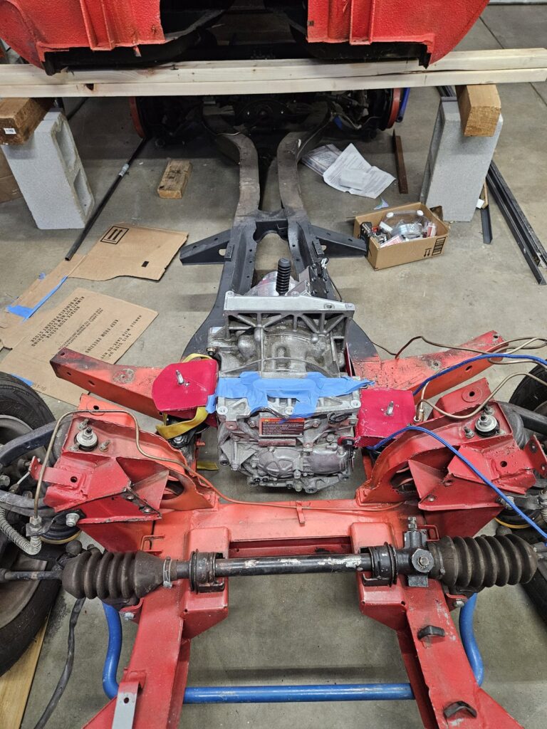
Rolling Chassis — Overhead View with Motor
An overhead view of the GT6 rolling chassis with the Leaf motor and TorqueBox sitting in the engine bay position. From above you can see the full geometry — front suspension, rack and pinion steering, and how the motor package sits relative to the frame rails. The blue tape marks position references for the motor mount fabrication.
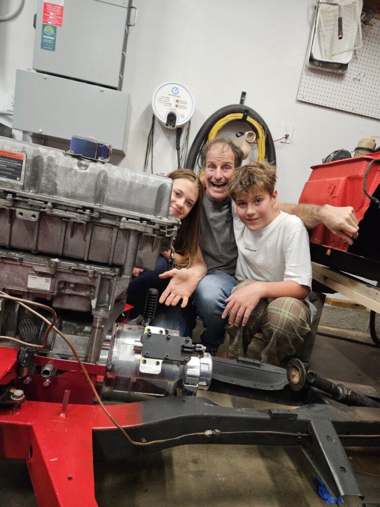
TorqueBox Fitted — Family Milestone Photo
A family milestone shot with the motor, TorqueBox, and front battery box all sitting together on the GT6 chassis for the first time. The polished TorqueBox reduction unit is clearly visible bolted to the Leaf motor output — it steps the motor's high-speed output down 1.9:1 before the driveshaft. The GT6's front suspension wishbones frame the picture below.
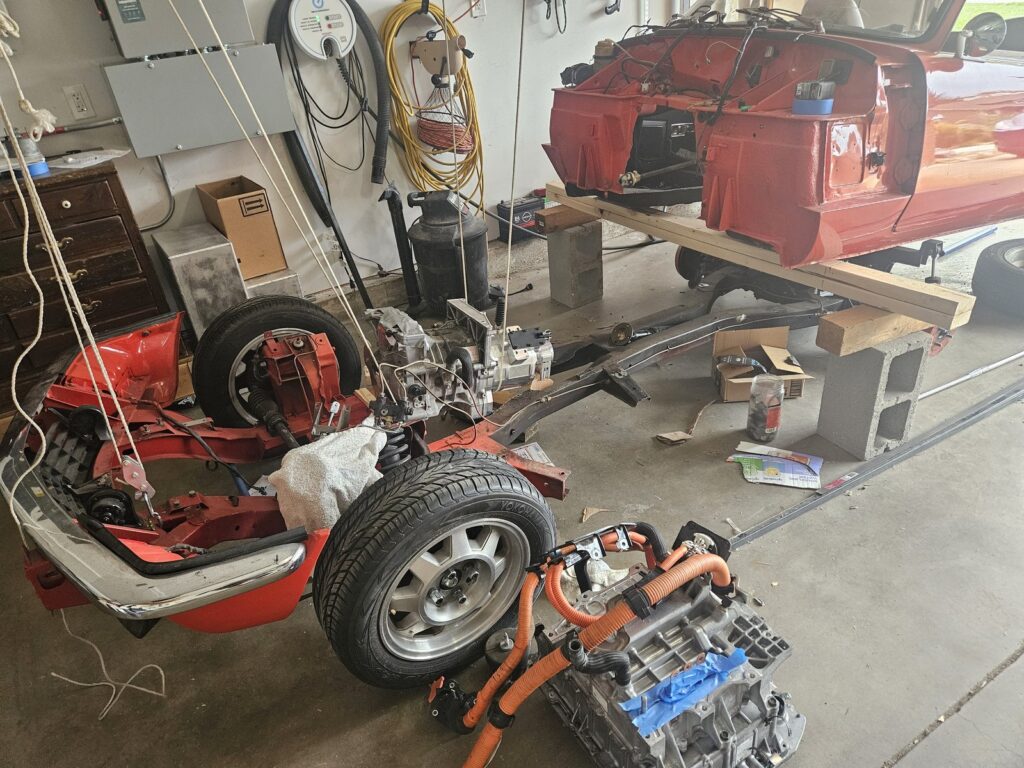
Rolling Chassis — Body Off for Motor Alignment
Separated body from chassis to align the motor with the driveshaft. Classic Spitfire technique. The EV wall charger on the garage wall will eventually supply the car's daily charge once road-legal.
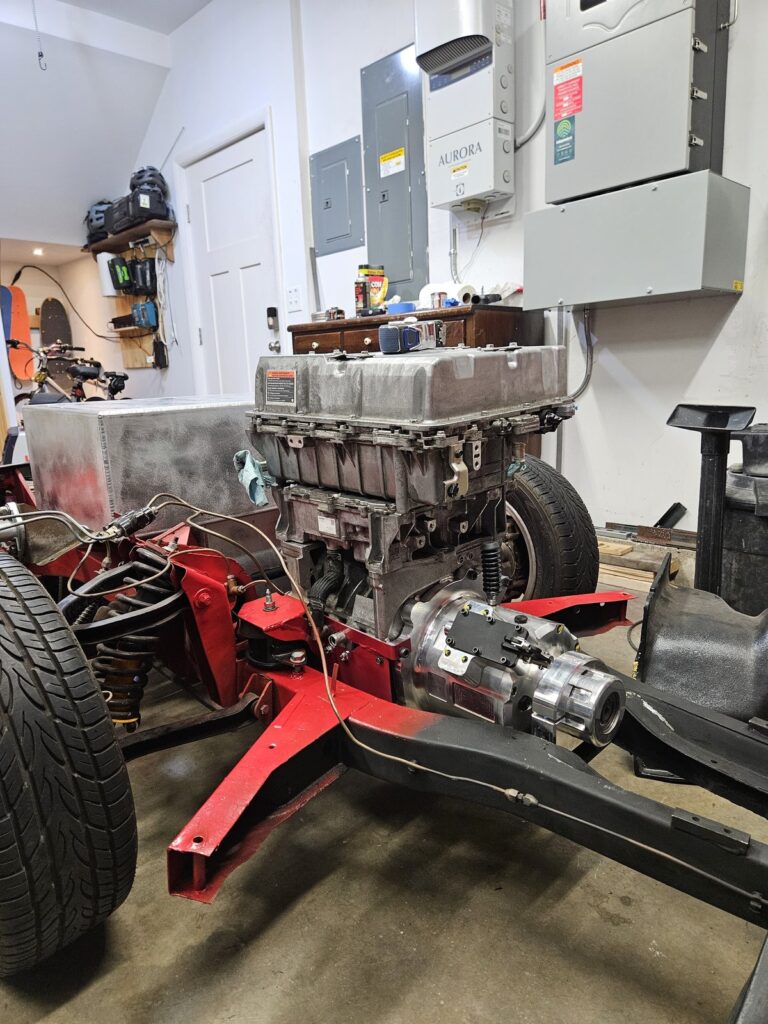
Motor Fitting — Body Off, Measurements Confirmed
With the Spitfire body lifted clear of the GT6 chassis, the Leaf motor drops into the engine bay for a test fit. The TorqueBox 1.9:1 reduction unit is already bolted to the motor output — this was the critical measurement session to confirm the motor mounts and driveshaft alignment before fabricating the permanent brackets.
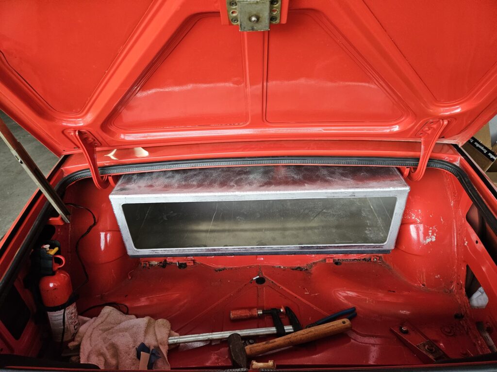
Rear Battery Box — Clean Fit in the Boot
The rear battery module fits almost perfectly in the boot where the spare tyre once lived. Custom aluminium enclosure fabricated to match the boot width exactly. Completely hidden when the lid closes, and improves weight distribution.
Motor Into the Bay — It Fits!
The moment we'd been planning for: motor and inverter sitting inside the Spitfire engine bay with HV orange cables routed. Custom fabricated aluminium battery box visible at the front. The Hobart welder did a lot of work on the motor mounts.
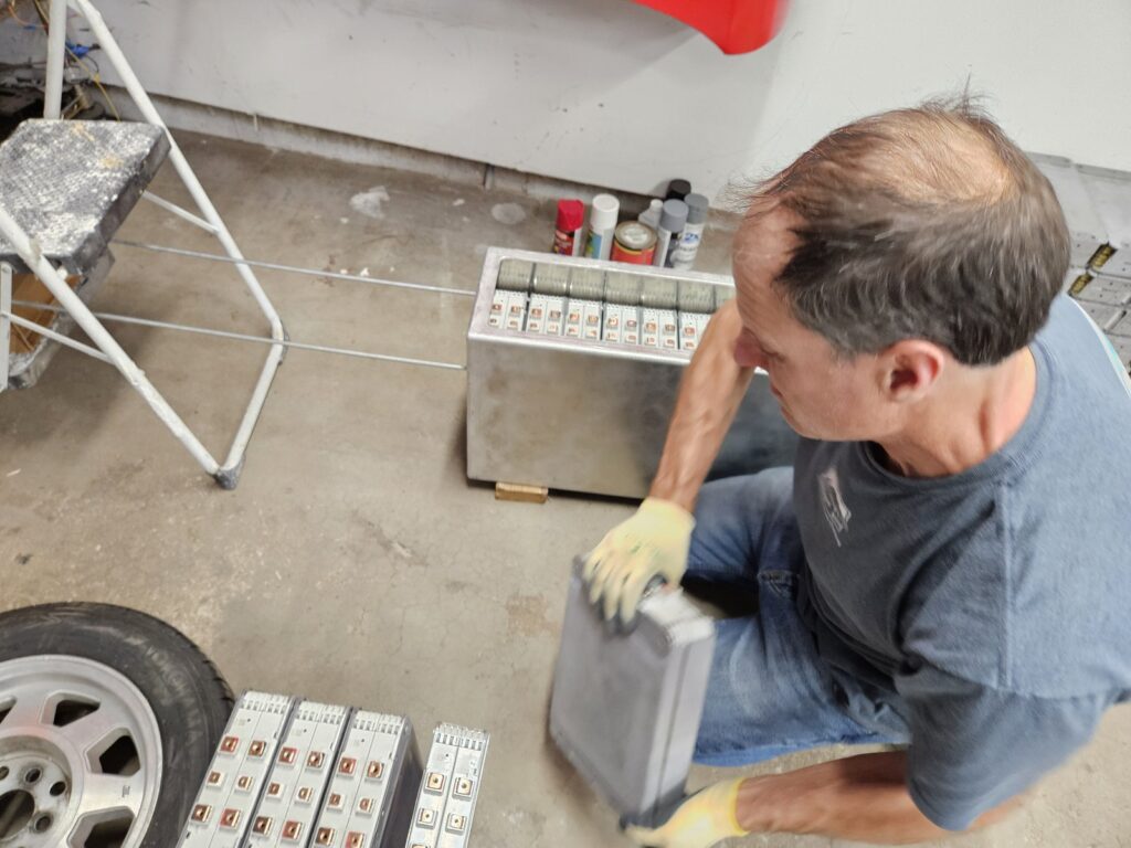
Opening the Leaf Battery Pack
The Leaf battery pack cracked open to reveal the pouch cell modules inside. Each module contains a stack of lithium pouch cells separated by orange plastic frames — the entire 40 kWh pack is made up of these modules. We inspected each one for damage before deciding which sections to use and how to package them in the Spitfire.
Family Photo with the Leaf Motor
The complete Leaf motor and inverter assembly on a rolling cart, ready for fitment planning. The orange HV cables run from the inverter casting down to the motor. The Spitfire body is visible in the background — this is the moment the two halves of the project first shared the same space.
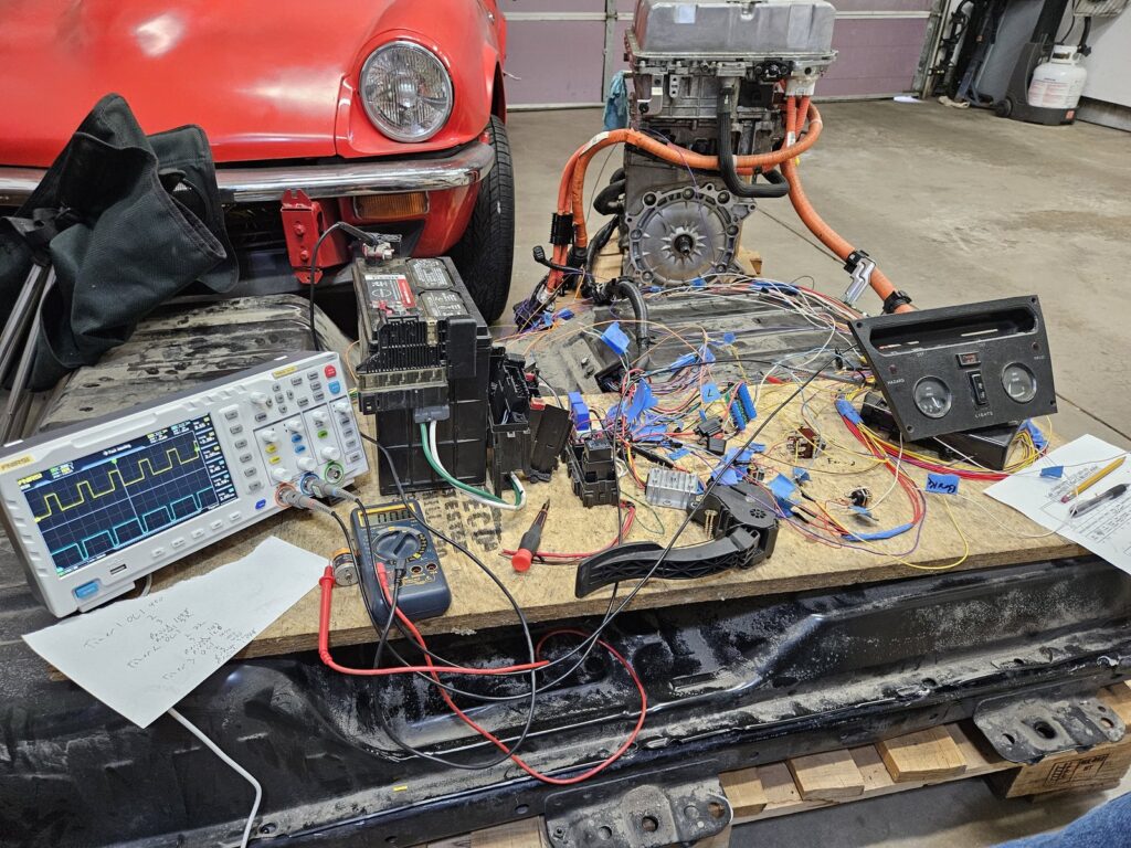
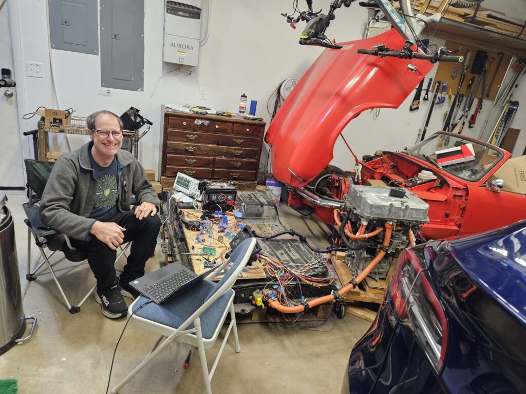
Wiring Deep Dive — Oscilloscope & Signal Mapping
The hardest phase: fully understanding the donor electrical architecture. Oscilloscope tracing throttle position signals, multimeter mapping every HV connector, hand-written notes capturing pulse widths at each test point.
GT6 Rolling Chassis — Early Wiring Assessment
The GT6 rolling chassis with the original Lucas wiring loom still in place. Before touching anything we documented every circuit, traced every wire, and decided what to keep and what to replace. The GT6's stronger chassis and uprated suspension are clearly visible — a much better foundation than the stock Spitfire frame.
Early Bench Testing — Getting the Electronics Talking
Before touching the Spitfire, we spent time understanding the donor CAN bus and BMS signals on the bench. This phase saved weeks of troubleshooting later. The original Spitfire switch panel sits on the bench — it will become the EV control panel.
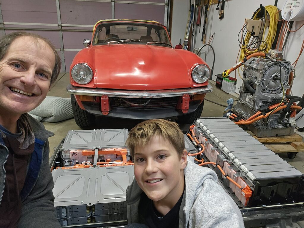
Battery Packs & Motor — Surveying the Goods
Laid out the complete EV drivetrain in the garage alongside the Spitfire for a size reality check. The motor unit is surprisingly compact. My son helped measure and we started planning how to package everything.
Hauling the Donor Car Home
With the deal done, the stripped donor was loaded onto a trailer and brought home. Engine bay completely bare — radiator, fascia and ancillaries already removed. Everything we needed was in those orange high-voltage cables.
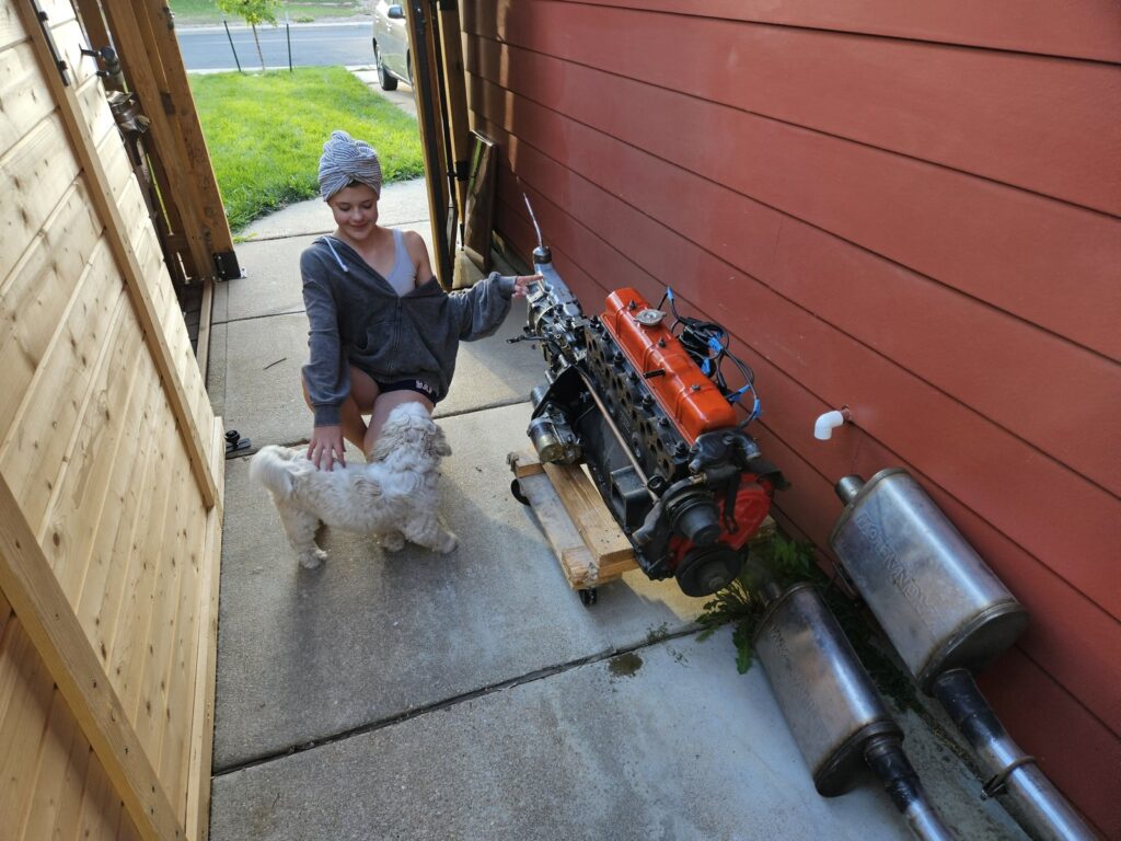
Spitfire CO2 emitters removed —
The Spitfire had all its driveline removed. The gearbox was trashed and the motor had water in the oil. We parted out the good parts and sold them on ebay. Things like the dual mikuni carbs did ok but the overdrive sale didn't go as well. The overdrive was not in as good of shape as I thought so I refunded some of the cost to the buyer. Hopefully everyone was happy in the end. Overall this helped off the the cost by a little bit. :)
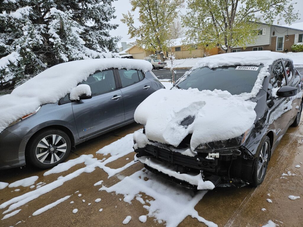
Sourcing the Donor — Snowy Day at the Yard
Found our 2020 Nissan Leaf S donor at a local salvage yard on a snowy September day — two Leafs side by side, the black one a write-off with an intact drivetrain. The complete Leaf stack — motor, inverter, battery, and wiring harness — was all there. We made the deal and started planning extraction.
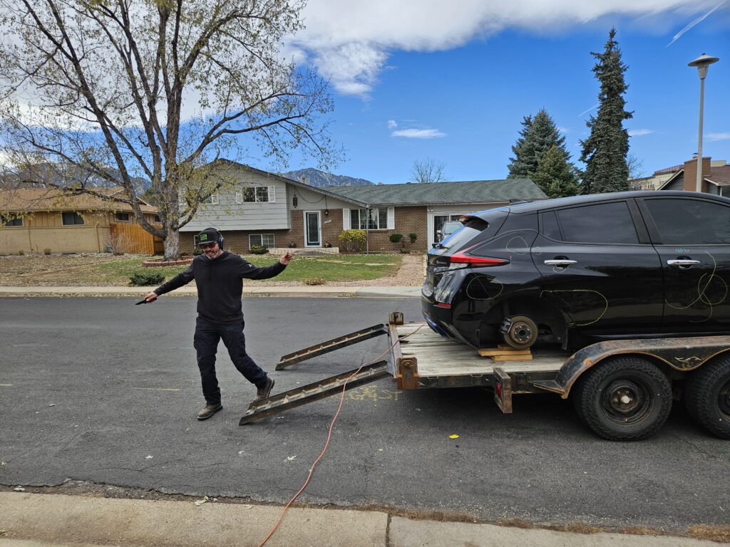
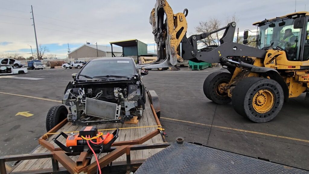
Haul Day — Unloading the Wrecked Leaf
Everything we needed from the Leaf had been removed and we had to unload the rest of the car. We sold the wheels and tires to a neighbor(Stefan) then called up Will. Will has a great trailer we loaded the car up on. Then it was off to the salvage yard. I think it cost more in gas to drive the car the the salvage yard than we got from the car. We got about $150 for the metal. I even had the old 6 cylinder block in the car. It was an experience I will not soon forget.
Because the car had no wheels they simply stabbed it's windows out with a fork lift and off it went. Next was the collection of the $150 where I had to go into a area protected by 10,000 Volt razor wire and bullet proof glass. Did they give me cash, no they didn't. I got a printout that I then took to a ATM type machine and it gave me the cash. I had no idea a scrap yard needed such security.
I have to thank Will for his time and getting to share the experience with him.
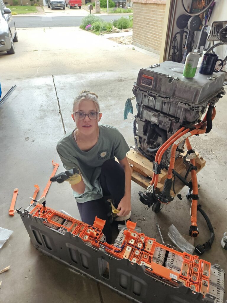
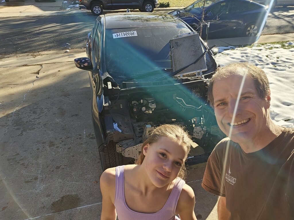
Finding the Donor — A Wrecked EV at the Yard
Tracked down a wrecked modern EV at a local salvage yard — low-mileage front-end write-off with battery, motor, inverter and BMS all intact. My daughter came along to inspect the find. This is where the project really began.